Description
Item specifics
● Condition : New
● Brand : Jolooyo
● Type : NAP135
● Country/Region of Manufacture : China
● To Fit : Amplifier
It is based on the core circuit of the Naim NAP135 Power Amplifier.
Tech highlights:
Fully Discrete.
75W AB.
Monarual design.
single-point grounding, ground resistance is close to the 0.02 ohm, low noise design.
PCB is small and flexible, very friendly for all kinds of chassis installation.
More cost-effective sound modification potential.
Integrated protection circuit
Maximum input voltage:2.6VPP
Gain: 28X
input resistance: 100K
Output Power: 75W 8Ω(AB)
Product configuration
DIY kit: Contains the PCB and the components needed on the PCB.
Finished board: Based on the well-tested board on the standard version kit, we verified all key points voltage, and used the signal generator and oscilloscope for analog waveform double verification. We will not use this board for listening test.
All finished pcbs are all carefully hand-soldered and fully tests, so the price is higher and less cost performance. Price-sensitive consumers but with have DIY ability are recommended to choose the kit.
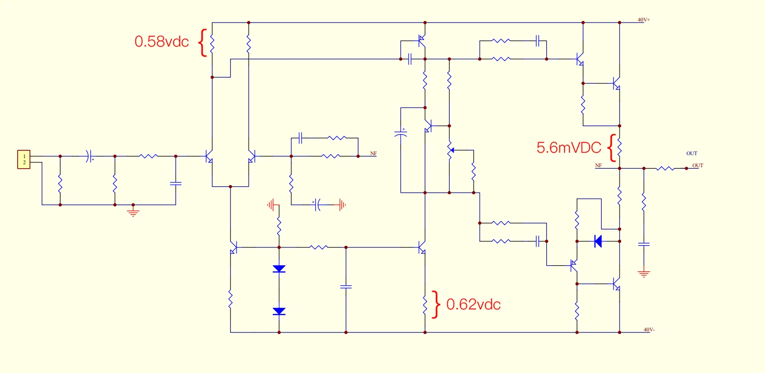
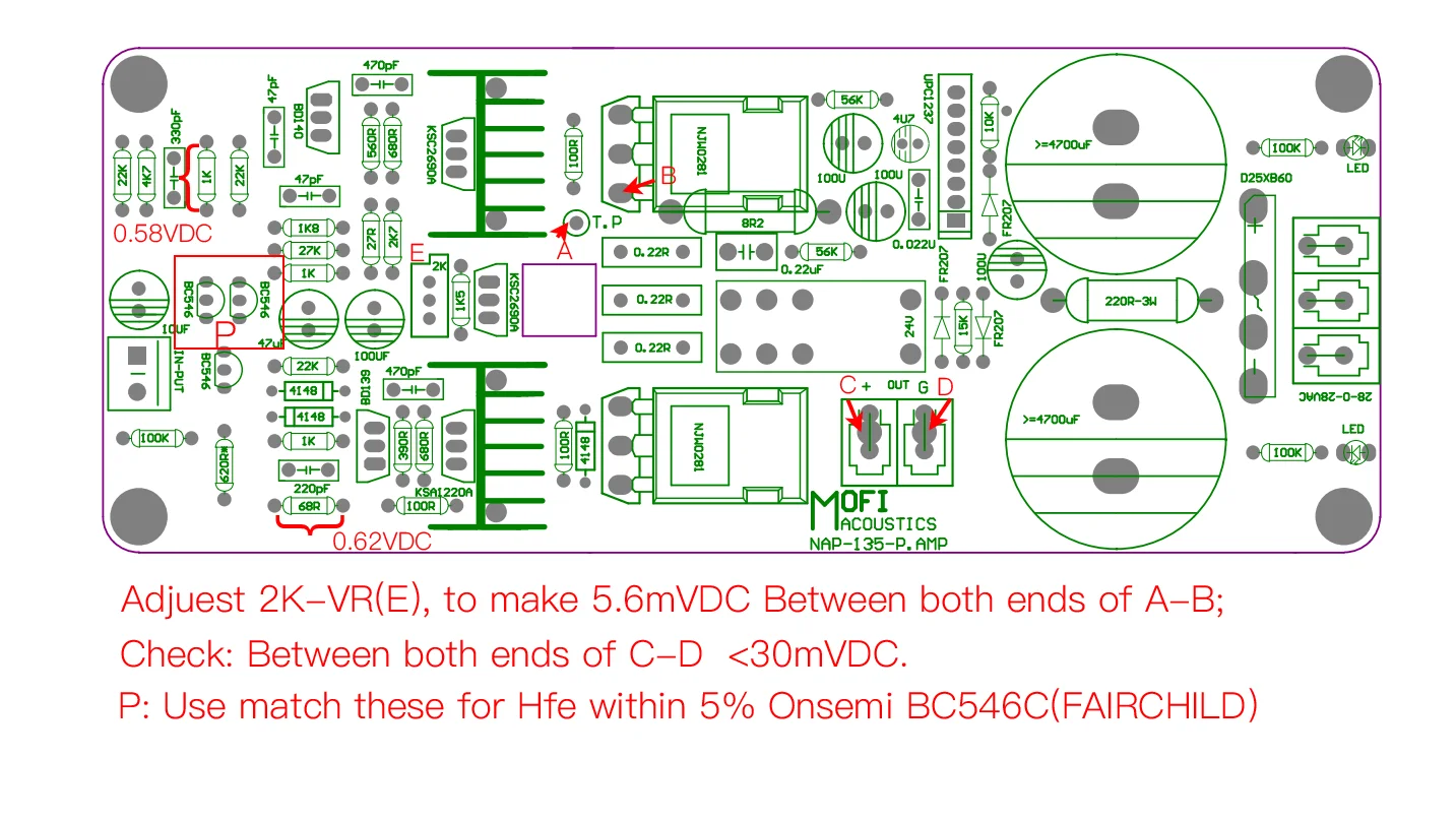
Schematic & key point of debugging
PCB comes with component parameters for easy installation.
We only refer the schematic of the amplification part of the circuit. If you need full circuit parameter, please read the component value with the PCB by yourself; we do not provide additionally.
please keep test point voltage close enough to it, +-20% is also permitted.
DIY KIT Instructions
Since the PCB holes are plated through, you only need to solder the parts from the bottom of the board. Do not drill or enlarge the holes because that would damage the through-plating.
Clean both sides of the blank PCB with paper towel and isopropyl alcohol or electronics flux remover, then solder the components to the board, starting with the lowest profile parts.
Make sure the correct part goes into each position on the circuit board. Measure each resistor with your multimeter to ensure its the proper value.
Clean up the solder flux residue from the board with isopropyl alcohol (or electronics flux remover) and a brush.
Inspect all solder connections carefully, using a magnifying glass, to make sure there are no solder bridges or cold solder joints. Use a multimeter in ohms scale to check for short circuits. As a minimum, you should verify that the V+ and V- DC inputs are not shorted to ground, or to each other, and that the output pad isnt shorted to ground. Correct any mistakes before proceeding to the next phase.
Tips:
please prepare external heatsink.
Adjust 2K-VR clockwise to the maximum resistance value before powering on.
After power-on, slowly adjust 2K-VR counterclockwise until 5.6mVDC can be measured between A-B.
Parts list

Pics
DIY KIT

Pics
Finished Board

Shippment:
1.We provide shipping to international via China Post Airmail, and every parcel will be registered with tracking number. We can also ship by UPS/EMS/DHL/FedEx for alternative shipping method for corresponding . Please let us know before payment if you need split shipment.
2.International shipping requires complicated shipping procedures (such as both countries customs, transit stations etc.), also will be affected by many factors, such as holidays, weather conditions etc, If you have not received your shipment from payment, please contact us.
3.Time of Delivery:Based on the China Post Airmail and our experience, kindly please be noted that To United States / United Kingdom / Australia, it takes around 10-15 business days; To Canada, it takes around 12-18 business days; To Brazil / South America, it takes around 25-35 business days. To Italy / France / Spain / Germany/ Eastern Europe, it takes aournd 15-20 business days.
& Replacements & Repair:
We accept s & replacements from the day the customer receive the products, please make first contact from receiving the order. Products should be in original condition. As a benefit to our customers, we also provide repair within 3 months from the day when this item is shipped out, after repair is done, we will send you the item, but the customer should pay both shipping ways.
Feedback:
1)Your Feedback is really important to us, please take a few seconds to leave great feedback if you are satisfied with our product or service, thank you so much!
2)We always offer the lowest price for best goods and service to you.
3) Please contact us before leaving neutral(3 stars) or negative(1-2 stars) feedback.We will try our best to solve the problem and leave you a happy shopping mood here. Thank you!
